Heightmap / Surface Leveling
AstroCore can scan the surface of the CNC table by probing at multiple points and building a height map. This is useful when the table or workpiece is not perfectly flat — the height map allows the application to compensate for any unevenness by adjusting the Z axis in real time while running a program.
Setting up the grid
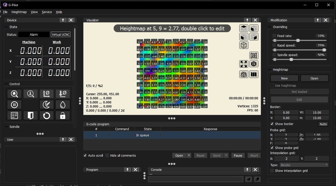
Before scanning, you need to define a grid — a mesh of probe points placed over the working area. The grid is configured in the heightmap panel: you set its position, size, and the number of probe points in each direction.
Scanning
Once the grid is configured, the Scan table function moves the tool to each grid vertex in sequence and probes the surface height at that point. The machine must be connected and the probe must be set up correctly before starting.
Viewing the result
The scanned surface can be viewed in two ways:
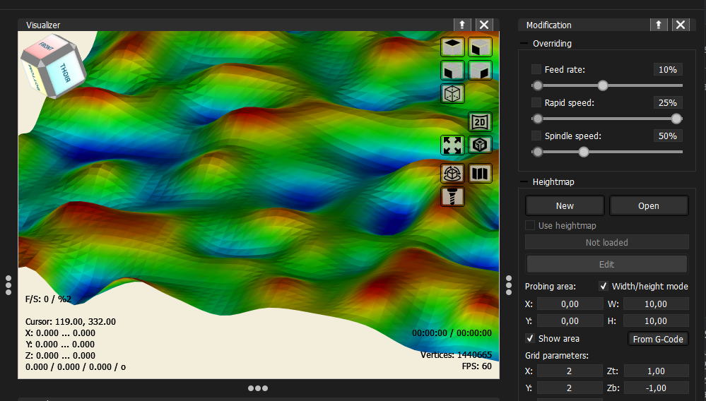
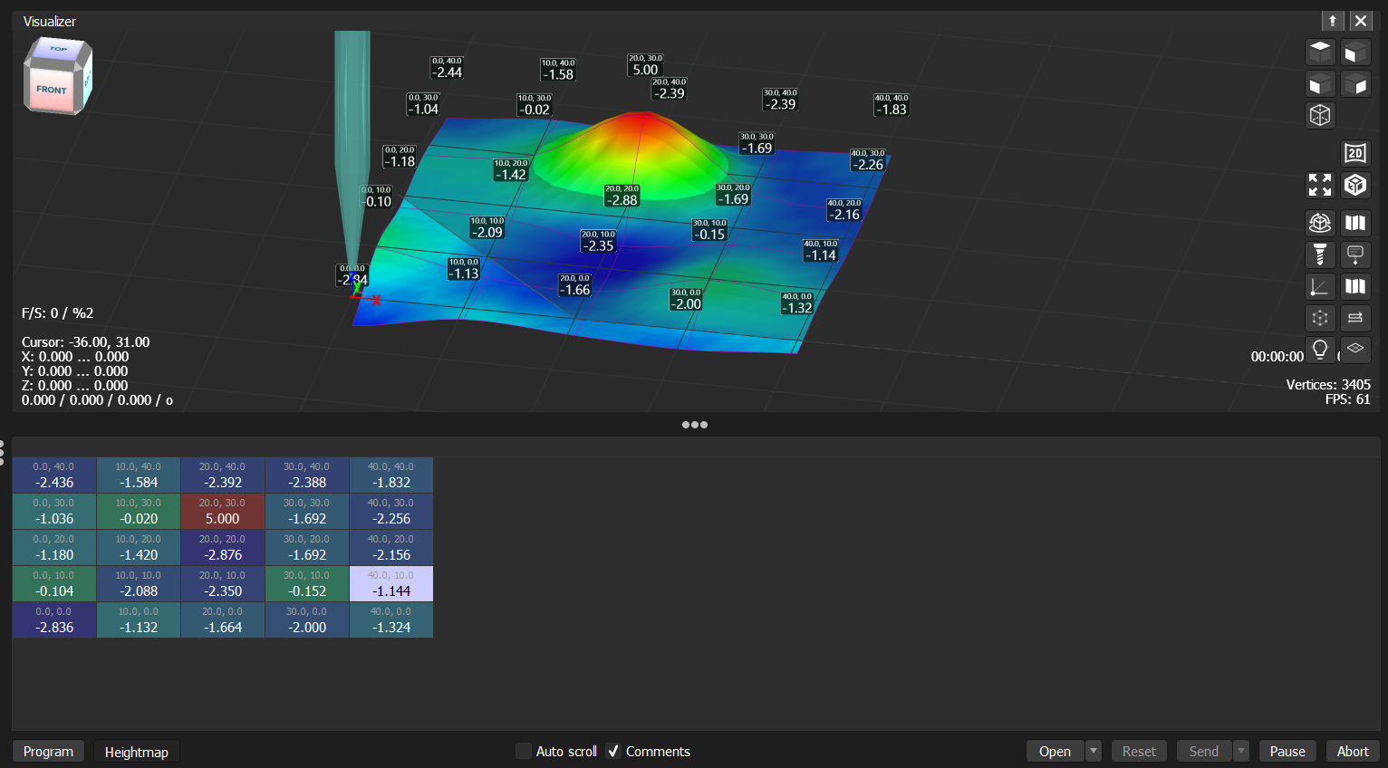
- Visualizer — the 3D view shows the heightmap as a colored surface overlaid on the working area. Colors represent height — from blue (low) to red (high). Height markers can be displayed at each probe point by enabling the marker overlay in the visualizer.
- Heightmap table — switching to the heightmap view in the program panel shows the probed values as a grid table. Each cell displays the X, Y position of the probe point and the measured height.
Manual editing
Any individual height value can be edited manually:
- In the visualizer — click a height marker to edit its value directly.
- In the table — click any cell and type the new value.
This is useful for correcting a bad probe reading or filling in a point that was not probed.
Interpolation
Between the probed grid points, the application interpolates the surface to compute the Z correction for any position in the working area. Several interpolation methods are available (Bicubic, Bilinear, Linear, Nearest Neighbour). Bicubic produces the smoothest result.